580 m HDD in extremely difficult ground
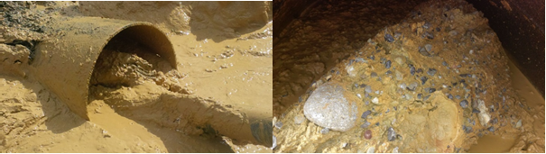
The soil consisted of layers of sand and mudstone, marl and gravel with boulders, superimposed by 20 – 30 m gravel with stones and boulders.TIGF is the major gas network owner in South West France and is facing on some of its networks the demand to perform system improvements. In compliance with these improvements, a gas line, DN 350, located between the communities of Allier and Momères near the offshoots of the northern Pyrenees, needed replacing.

 01.12.2015
Author: Dipl.-Ing. Ernst Fengler, Managing Director, LMR Drilling GmbH
LMR Drilling GmbH installed a 580 m gas pipeline DN 350 in a nature reserve under the River Adour in Bernac-Debat (southern France) for the major gas network owner, TIGF.
The soil consisted of layers of sand and mudstone, marl and gravel with boulders, superimposed by 20 - 30 m gravel with stones and boulders.
TIGF is the major gas network owner in South West France and is facing on some of its networks the demand to perform system improvements. In compliance with these improvements, a gas line, DN 350, located between the communities of Allier and Momères near the offshoots of the northern Pyrenees, needed replacing. The River Adour, located between the aforementioned villages, is crossed by that gas line which was installed more than 30 years ago by conventional open trench method. Today, and after many spring water related floodings later, the river valley is declared a nature protected zone (Nature 2000) and the pipe is a potential obstacle, as all these floodings are related to aspects of strong erosion.
Rethinking the above circumstances, TIGF had to do something. Engineering advice was sought and, as a result of that, the decision was made to install a new pipe via the HDD method. After installation of the new pipe, the old pipe would be de-installed and the natural habitat could be left to redevelop as per the last hundreds of millions of years.
Before any of that could happen, TIGF undertook soil investigations. These showed a top layer consisting of gravel, boulders and stones. That layer had a thickness of 20 – 30 m. Below that layer, a conglomerate of layers of sand stone, clay stone, marl, sands, cemented sands, gravel and boulders could be found. In that conglomerate of “soils”, some bands of probably drillable sand stone, clay stone, marl, sands were identified, regretfully neither on a continuous basis, nor of horizontal or straight alignment.
The above soils were summarized in a soil investigation report with a feasibility, engineering and design report by the company, FOREXI. That report suggested the installation of casing pipes on both sides of the crossing. No drilling technique exists to date allowing the drill to be centralized enough to drill from one side into the casing pipe on the other side of the drill. The crossing was thus drilled from both sides with the drill meeting in the middle known as the intersect technique. Such an operation normally demands a straight section of a minimum 150 – 200 m.
When the above mentioned study was received with the tender documents, LMR scrutinized these – and held their breath. Though LMR had successfully completed HDD intercept projects over the course of the past 10 years (all of these being of far longer lengths, 2626 – 3946 m), LMR have never faced on any of these projects such challenging soil conditions.
As such, a reliable and robust approach had to be developed. First, a safe and economic installation method to install the casing pipes had to be identified. After some investigations, the research ended with a specialised company from Finland, with whom LMR had done similar works in the past, but not with casing extending to the depth required on this project. The DN 800 casing pipe had to be installed over lengths of up to 120 m. Some pre-meetings and a site visit with that company from Finland were used to elaborate customised solutions and to optimise the casing installation process.
Parallel to that, the drilling operations were engineered and re-viewed in close cooperation with an HDD borehole steering engineering association, Prime Horizontal.
Furthermore, coordination meetings took place with SPAC, a leading French pipeline contractor, with whom LMR were bidding these works as a Joint Venture.
All the above efforts concluded in the submission of a well-engineered solution – which was awarded after only one bid meeting.
Then works began.
The detailed engineering was finalised within less than a month – a result of many years of successful HDD projects.
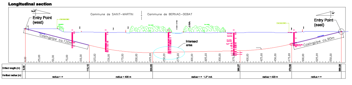
Above operations led to a drilling profile as described below:
Entry point West:
Entry Angle: 14.5°
Straight section up to MD 115.10 m, 120 m of these cased with a casing DN 800
Curved section from MD 115.10 m to MD 229.05 m with a radius of 420 m
Straight section with 1.2° inclination upwards from MD 229.05 m to MD 386.27 m
Curved section from MD 386.27 m to MD 479.08 m with a radius of 420 m
Straight section with 14° inclination upwards from MD 479.08 m to MD 568.58 m, 90 m of these cased with a casing DN 800
Exit Point = pipe site EAST
Upon verification and acceptance by TIGF of the final and detailed engineering, preparative works started. Access roads were built, drill sites and rig anchors were prepared and pipe works began.
After the rig anchors were in place, the Finnish specialist arrived and installed the two casing pipes. This was executed first on the west side and did not go according to plan. A major tool broke in the casing pipe which had already been installed to a depth of 42 m deep. A retrieval operation led by LMR took place and, after only 4 days, the casing pipe was recovered without major damage. The broken tool was replaced and then the casing pipe installed. The installation took place under close supervision of FOREXI, the TIGF’s (geological) engineer and HDD specialist. Soil samples, periodically retrieved during the casing pipe installation process, were analysed. The casing installation for both pipes was stopped after ~100 m based on the analysis of the soils which indicated the upper layer of boulders and gravels had been passed through. After the Finnish specialist had demobilised, the HDD spread was mobilised to site and rigged up – drilling operations began.
First, centralisation sleeves had to be installed inside the casing pipes.
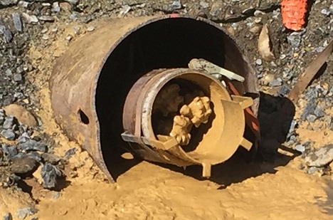
Then, the pilot drilling began. Both drilling assemblies consisted of 9⅞” tri-cone roller bits, mud motors, non-magnetic drill pipes and a special steering assembly.
After the pilot assembly had passed through the casing, pilot drilling quickly became a challenge. Soils encountered were of utmost heterogeneous nature, the drillable layers, indicated in the soil investigation report, where rarely found. However, drilling progress was made and after some time the target area for the intercept was reached. Encountering much more difficult ground conditions than anticipated reduced the chances of a successful intersect. Even worse, the targeted length for the intercept operation had to be reduced to only 30 m. That put the complete HDD operation at stake. After 4 attempts for the intercept failed, HDD works were halted to reflect the given situation and review options and solutions. The decision was taken to grout a section of the borehole and then retry the intercept. Regretfully, attempt 5 failed, and another grouting operation commenced. Then, finally, the sixth attempt succeeded and the intercept was completed.
This was a great relief for all parties involved, although at this stage further works were still to come to realise a successful conclusion. Pilot drilling had shown that rather long sections of the borehole were crossing gravel layers. These are generally a problem in HDD, as gravel is difficult to be removed from the borehole with mud systems.
Reflecting the above, pilot drilling operations were finished as shown below:
Entry point West:
Entry Angle: 16.5°
Straight section up to MD 107.44 m, 104 m cased with a casing DN 800
Curved section from MD 107.44 m to MD 212.14 m with a radius of 420 m
Straight section with 1.3° inclination upwards from MD 212.14 m to MD 383.43 m
Curved section from MD 383.43 m to MD 469.71 m with a radius of 420 m
Straight section with 14° inclination upwards from MD 212.14 m to MD 577.77 m, 103.40 m cased with a casing DN 800
Exit Point = pipe site EAST
Reaming operations started well with a 22” milled-tooth hole opener and were finished within a week. Again, soft and hard spots were encountered along with the gravel layers. The last 200 m saw plenty of gravel flushed to the surface.
The mud system, well-engineered by HEADS, now had a mud engineer assigned to the drill operations permanently on site, and managed to thicken the mud in a way that stones up to 100 mm could be flushed to the surface. However, once aware of these stones in the borehole, the decision was taken to perform a combined check and wiper trip. That aimed; (a) to get away from the borehole more gravel and stones, which were probably subject of sedimentation before; and (b) to verify the later passage of the 14” product pipe. An 18” barrel reamer was used for this operation. The combined check and wiper trip was done in less than 8 hrs, bringing once again plenty of stone and gravel to the surface, but showed also that torque and pull forces were extremely low. Therefore, the borehole was considered to be in a good condition to pull the pipe.
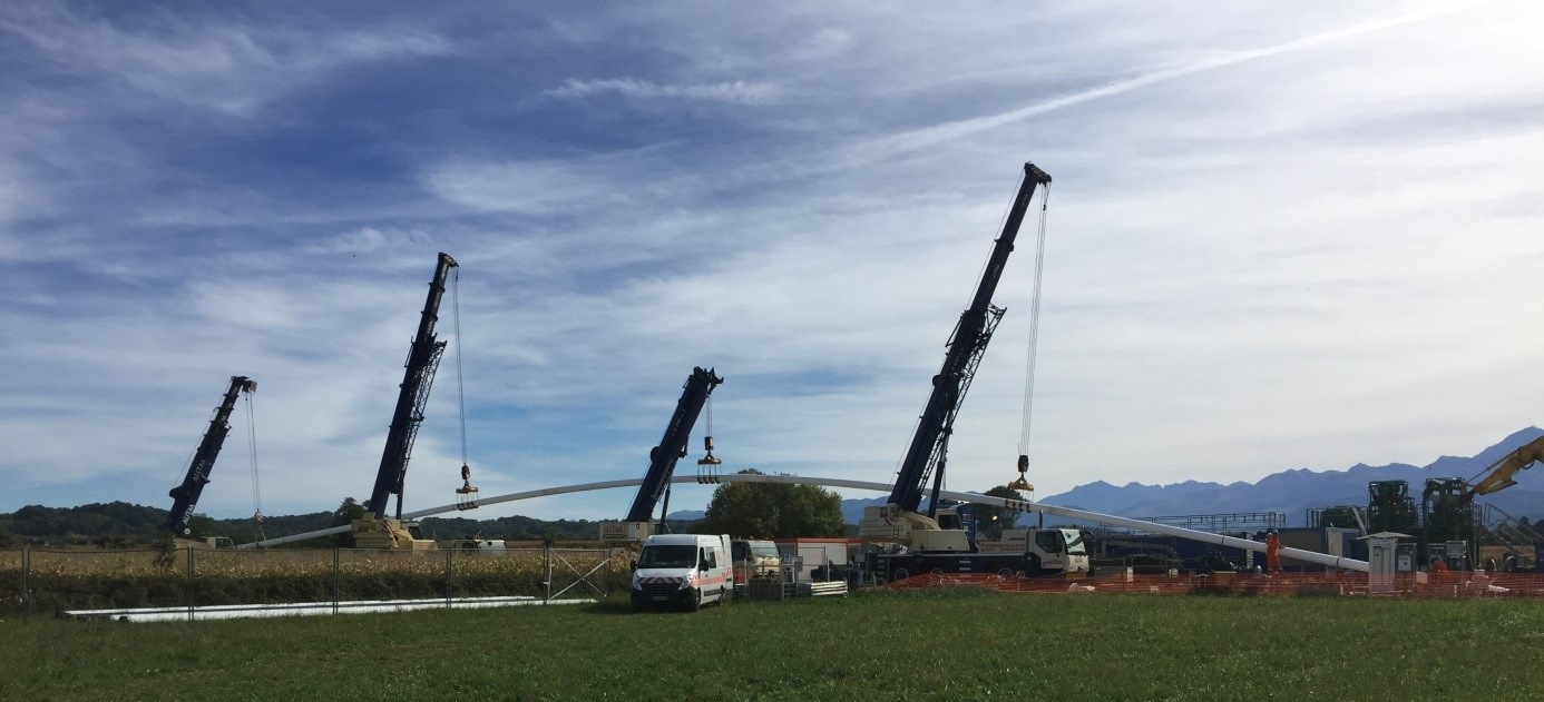
As a consequence, the pullback was arranged for the day after, Saturday, October 10th. Early in the morning, cranes were positioned at pipe site to lift the product pipe in a proper curved profile (named catback or overbend). The pipe was pulled into position and then the pullback operation began.
Pulling the pipe was not a spectacular operation compared to previous projects and encountered some ups and down. The casing pipe at East Site (i.e. pipe site) was easily passed. After 4 hours, the pulling assembly entered the casing at the West Site without problems. On the final pulling phase, in the West, casing grouting operations took place parallel to the pulling process. These were required as the Client, TIGF, demanded applying a special system to avoid contact between the product pipe and the casing pipe. In this case, a liquid thermal clay system was used with great success. During this last pulling process, spacers and two grout lines HDPE OD 63 mm were attached to the product pipe at the East side. These were used the day after pullback to displace mud and to grout the eastern casing pipe. Displacement of mud was achieved by the airlifting method, which could be applied with success due to the fact that the casing pipe could be used as a close body. Finally, this was completed as well and the job was done.
Afterwards, HDD equipment was rigged down and sent away to the next job site.
A glad and relieved client was left on site with a newly and safely installed gas line.
all newsCareer

Large company, great appreciation, great opportunities: As part of the Ludwig Freytag Group, LMR Drilling offers you great prospects. See for yourself!